Unrolled 3D confocal measurements of turning parts


Unrolled 3D confocal measurements of turning parts full article
C. Bermudez1, A. Matilla1, J. Mariné1, D. Martínez1, C. Cadevall1, R. Artigas1
1 Sensofar-Tech, S.L. (Spain)
May 2017
Euspen 17th Intenational Conference, Confocal Microscopy
Abstract
Three-dimensional measurement of cylindrical surfaces is today accomplished with the use of an optical measurement system and dedicated rotational stages. The optical instrument is typically a sensor head that is able to provide 3D data with Confocal, Focus Variation or Coherence Scanning Interferometry, having every measurement technique its own benefits and weaknesses. Cylindrical measurements are commonly taken field by field by rotating the sample and stitching all the fields. The main drawback of this method is the fact that the field distortion, and residual flatness error are slope dependant, and only corrected for flat samples, which is not the case due to the cylindrical shape. In this paper we propose the use of a rotational stage with the combination of a slit-confocal imaging system capable of acquiring unrolled confocal images with a line-scan approach while the sample is rotated at constant speed. Three-dimensional measurements of cylindrical surfaces are taken minimizing the errors appearing on the field stitching technique. This new 3D acquisition method is applied to the chatter marks characterization appearing on turning parts.
1. Introduction
Confocal microscopes are widely used for areal measurements thanks to its good height resolution and the capability to measure high local slopes. For the measurement of large areas while keeping few nm of system noise, it is needed to use high numerical aperture objectives, move the sample in the XY plane and stitch several fields together to cover the required surface. Other technologies such as Coherence Scanning Interferometry (CSI) and Focus Variation (FV) [1] are also widely used for the measurement of technical surfaces. Each technology has its own advantages and disadvantages. For instance, Interferometry provides the highest vertical resolution independently of the numerical aperture of the objective, but it has the drawback of being highly sensitive to vibrations and requires a dense Z scan to extract the areal information. Focus Variation has the benefit of being very robust for the measurement of rough surfaces, but it requires high numerical aperture to achieve high vertical resolution. For low magnification objectives, Focus Variation is more suitable to measure the form and waviness components of a surface more than its texture, due to its limited lateral resolution. In this paper we are proposing the measurement of cylindrical surfaces, which in principle can be measured with any of the above technologies. We have selected Confocal as the first step in our research to implement this new acquisition methodology, despite this does not limit the use of CSI or FV in future developments.
2. Method
On cylindrical surfaces a rotational stage is used to measure fields along the round surface and stitch them in order to obtain a complete 3D measurement. The required amount of fields depends on the microscope’s magnification, as well as on the cylinder diameter. In addition, for small diameters, if the local shape reaches slopes not suitable for the objective under use, the active field of the camera has to be reduced, leading to an increase of the required number of fields to be measured and stitched. This is even more evident when measuring the cylinder shape with low magnification optics, where the maximum permissible local slope is relatively low, and thus the suitable field of the camera used is even less.
The main drawback of this method is the fact that the field distortion, and residual flatness error are slope dependant and only corrected for flat samples, which is not the case due to the cylindrical shape of the sample. Calibration of Confocal measurements on tilted surfaces is not as simple as removing the residual flatness error taken on a flat reference mirror. The original raw aberration of the optics changes the field curvature amount with the tilt of the imaging object, generating a low frequency error that increases in amplitude with the tilt. On cylindrical surfaces this is a continuous effect and is difficult to correct, and despite this error is usually lower than the texture components of the surface, it is revealed on the stitching between fields. Such error may be taken as a low frequency error of the surface itself, but in reality it is not.
In this paper we show a new approach for areal measurements of cylindrical surfaces that uses a rotational stage in combination with a slit projection confocal arrangement and a high-speed camera (Fig. 1). The slit is located on the field diaphragm position of the microscope and illuminated with an LED. Its image is projected onto the surface with a microscope objective. The reflected light goes back through the objective and is imaged onto a CMOS camera that can work as area, or single line sensor at much higher frame speed. An unrolled confocal image of the cylinder surface is built by rotating the sample and calculating the confocal intensity in the center of the slit. We have tried two confocal approaches. The first one, corresponding to one single pixel intensity or to the average sum of a number of them perpendicular to the pixel under investigation, depending on the magnification used. In our case, with a 20X 0.45 we have used one single pixel. The second method is the pixel gradient, corresponding to the square summation of the gradient values on the same perpendicular window [2]. The whole optical sensor head is mounted on two linear stages corresponding to X and Z directions shown in Figure 1, allowing the sensor to move through the focal region of the microscope, and to position the cylinder along its main rotational axis. A rotation stage is mounted in parallel to the sample rotation axis, allowing the sample to be positioned in every angular position with high precision and rotate it at a constant speed for the line-scan approach.

A set of 360º confocal images can be obtained at different heights of the sample relative to the sensor and used to calculate an unrolled areal measure of the cylinder.
This method has several advantages over the conventional one such as reduced measurement time, and no stitching required. The result shows less residual flatness error since the surface lies flat in the measurement direction in comparison to field measures where the highest slope regions will show field distortion and non-constant sampling.
3. Results
To proof the concept of unrolled areal measurements, we have used a Basler acA2000-50gc camera mounted on a 0.5X field lens, and a slit of 15 micron width projected onto the surface. A turned part of 6.0mm in diameter is hold on a 1000 steps/revolution stepper motor, model Orientalmotor PKP544MN18A and driven with a 1:250 microstepping controller. The camera is triggered at 1000 frames per second and 7 rows of pixels centered on the slit have been acquired. We used a 20X 0.45NA microscope objective acquiring the unrolled confocal images, and optimum Z increment steps of 1.0 micron to get a series of images. Every unrolled confocal image started at the same sample angle. Stepper motor controller generates an acceleration ramp and triggers the camera for the first time to start image acquisition as soon as the motor is rotating at the rated speed. Although being hardware-controlled, still some repeatability mismatch during the acquisition start trigger made the confocal images to be vertically shifted a few pixels. Therefore, after the acquisition, we have registered all the confocal image sequence with a translation-only registration algorithm, making every pixel in the Z stack to belong to the same point in the image.
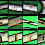
Registered unrolled series of confocal images are finally used to obtain the areal topography. Figure 2 shows the result of an areal measurement of a turned part. It is shown that the result has naturally removed the cylinder shape of the part. In the topography, not only ridges appear due to the feed in the horizontal direction, but also chatter marks in the vertical (axial) one due to tool vibrations.

4. Error influences
We have studied the influence on the areal measurements of wobble and run-out introduced by the rotational axis and the clamping mechanism. This two errors manifest on the measured topography as low frequency components that correspond to the periodicity of a full turn of the surface. By identifying such form errors from the series of the confocal images, it is possible to predict their amplitude and isolate the components on the topography subtracting them from the raw data. This method provides areal surface topography closer to the real one than any other existing method today.
5. Conclusions
We have shown a new optical measurement approach based on confocal microscopy for the measurement of cylindrical surfaces. This new optical method uses a slit projection and a rotational axis to acquire a series of unrolled confocal images and recover the three-dimensional surface topography. The method shows several advantages in front of conventional 3D methods such as no required stitching, simplified flatness error, and reduced overall measurement time.
References
[1] Leach, R., Optical Measurement of Surface Topography, Springer Verlag ISBN 978-3-642-12012-1 (2011)
[2] Artigas, R., Pinto, A.; Laguarta, F., Three-dimensional micromeasurements on smooth and rough surfaces with a new confocal optical profiler, Proc. SPIE 3824, 93 (1999)