付加製造におけるプロセス誘起の形状および表面性状の変化の特徴付け


カタルーニャ工科大学(UPC)で学士号を取得。同大学物理学部に研究アシスタントとして勤務。バルセロナ大学(UB)で修士課程を修了した後、Sensofarに入社し光学測定の世界へ入る。セールススペシャリストとして、Sensofarの光学測定に関する知識を伝播し、Sensofarのシステムの可能性を最大限に引き出す方法について顧客にトレーニングを提供している。通常はSensofarのデモルームでサンプルを測定したり、ライブデモンストレーションを実施している。

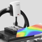
Sensofar 3Dプロフィロメータを使用すると、付加製造プロセスにおけるたった1つのパラメータにより、製造サンプルの形状がどのように変化するのか特徴付けることができます。また、固有の粗さパラメータを特定することで、異なる角度で印刷された表面を定量的に区別することができます。
この10年間で、従来のサブトラクティブ法や形成的手法に対する優位性から、付加製造が産業界で採用されるようになりました。付加製造によって製造可能となる複雑な形状は、従来の製造方法とは比較になりません。しかし、標準化が進んでいないこと、製造したサンプルの表面特性を制御ことが難しいこと、加えてほとんどの場合には後処理工程が必要になることなど、いくつかのデメリットもあります。本研究では、形状と表面性状を測定することで、1つのパラメータが製造部品の最終的な特性に与える変化を測定することを目指しました。
研究1.プロセスパラメータに相関する形状偏差
(材料・その他)
本ケーススタディでは、選択的レーザー溶融法(SLM)を用いて、2種類の異なる材料で同じ試験片を2回作成しました。これにより、材料の変更が製造部品の全体的な形状に与える影響を確認したいと考えました。試験材料としては、航空宇宙産業や医療産業で広く使用されていることから、チタン合金Ti6Al4Vおよびアルミニウム合金AlSi10Mgを使用しました。
S wideを使用して、これら2つのサンプルと参照サンプルを測定し、3D比較ソフトウェアで比較しました。

3D比較では、SLMで製造した部品と参照サンプルの違いが示されています。サンプル形状の端部ではより大きな偏差が見られますが、全体的な形状はどちらの材料でも維持されていることがわかります。しかし、アルミニウム合金で作られたサンプルの表面には、一部で大きな偏差が見られますが、これはボーリング効果に起因するものです[2]。
また、同じ材料で製造した2つのサンプルを使用し、SLM機の内部パラメータの1つ(ビーム補正)を変更して同様の試験を実施しました。今回は予想される偏差が小さかったため、参照サンプルではなくCADファイルを3D比較のリファレンスとして使用しました。
事実、この手法が製造を制御する最も適切な方法なのです。すなわち、CADモデルの各領域に交差を設定し、それに従って製造部品を解析することです。

In Figure 2, we can see the difference between one sample and the other, highlighting some of the critical points. We can also select a cross-section and analyze how the profile gets modified in each sample. The next step would be to go back to the manufacturing process and adjust the parameters so that the output is always what we expect.
STUDY 2. Surface texture changes as a function of printing angle
Surface texture of manufactured parts can be crucial to their functional performance. Therefore, understanding how the different variables in the additive manufacturing process can affect the different surface texture parameters is a hot research topic.
For this second case study, we manufactured different units of another test specimen (a square of 1 cm x 1 cm, 2-mm thick) but changing the printing angle. This is a common test among manufacturers and researchers that use additive manufacturing to understand the performance of their machine in these situations.
We measured surface texture on several locations of the different samples using our S neox 3D optical profilometer and positioning the samples perpendicular with respect to the optical axis. The measurements were then filtered according to ISO 25178 using the same nesting indexes to ensure meaningful comparison and finally compared using SensoPRO software to determine which parameters differentiate each group of measurements.

その結果、印刷角度が変化すると、表面性状が大きく変化することがわかりました。より具体的には、最も変化したパラメータの1つがSdr(展開面積比)であると結論付け、[3]と一致しました。Sdrパラメータは付加やコーティングに関連する応用で重要なため、接着とコーティングが機能的性能に関わる付加製造表面(疎水姓表面など)では印刷角度が重要となります。
On our first study, we were able to characterize how one single parameter from the additive manufacturing process can change the form of the produced sample. On the second one, we were also able to distinguish quantitatively samples printed at different angles through the identification of the characteristic surface texture parameters.
The S wide system, with Fringe Projection technology, was used for form measurements while the S neox was used for surface roughness measurement. In the case of the S neox, Ai Focus Variation technology was chosen to be the proper technique for the measurement of micron-level roughness because of its speed and HDR mode. However, Confocal and Interferometry technologies (also included in the same system) are being used to characterize a wide range of additive manufacturing parts, from as-built surfaces to smooth post-processed surfaces. The versatility of the S neox has been proven to be very useful thanks to the integration of different optical metrology technologies in the same system.
[1] A. Townsend, N. Senin, L. Blunt, R.K.Leach, J.S.Taylor, “Surface texture metrology for metal additive manufacturing: a review”, Precision Engineering, Volume 46, 2016, Pages 34-47
[2] Bourel, D.I., Marcus, H.L., Barlow, J.W. and Beaman, J.J.(1992), “Selective laser sintering of metal andceramics”, Int. J. Powder Met., Vol. 28 No. 4,pp.369-81
[3] Grimm T, Wior G, Witt G. “Characterization of typical surface effects inadditive manufacturing with confocal microscopy”.Surf Topogr: Metrol Prop2015;3:014001

関連製品